Introduction
I've recently acquired a Starlight Xpress Filter Wheel and Off-Axis Guider to go with my Starlight Xpress SXVR-H18. One of the first things that needed doing was to ensure that the chip is correctly collimated with the optical axis.
When the SXVR-H18 is fitted to the filter wheel, the T-Threaded ring is removed and replaced by a special plate for the SXVR-H18. This plate requires accurate collimation with the chip in the camera, as the plate will be inline with the optical axis of the telescope.
My solution, which I dreamt up whilst sufferring a bout of insomnia involves using a standard low power green laser pointer and using the reflections from the laser to align the plate and the chip.
The Setup
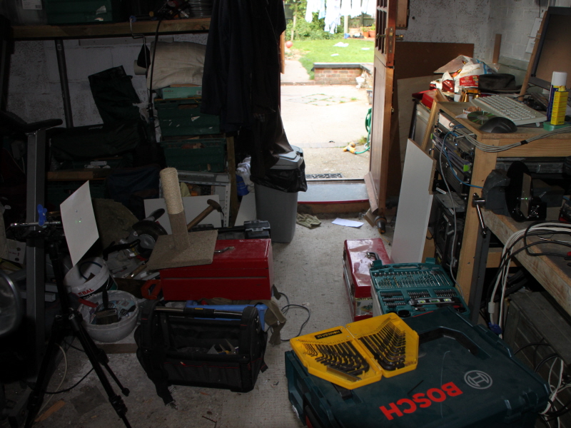
The green laser pointer (a low power one) was mounted on a tripod, and I made a simple bracket from a shelving bracket and a short dovetail bar. This was then aimed just to the side of my workbench vice. The camera and plate were then mounted in the vice. The screen is a sheet of paper laminated and cut down to size.
Step 1: Collimating the Plate
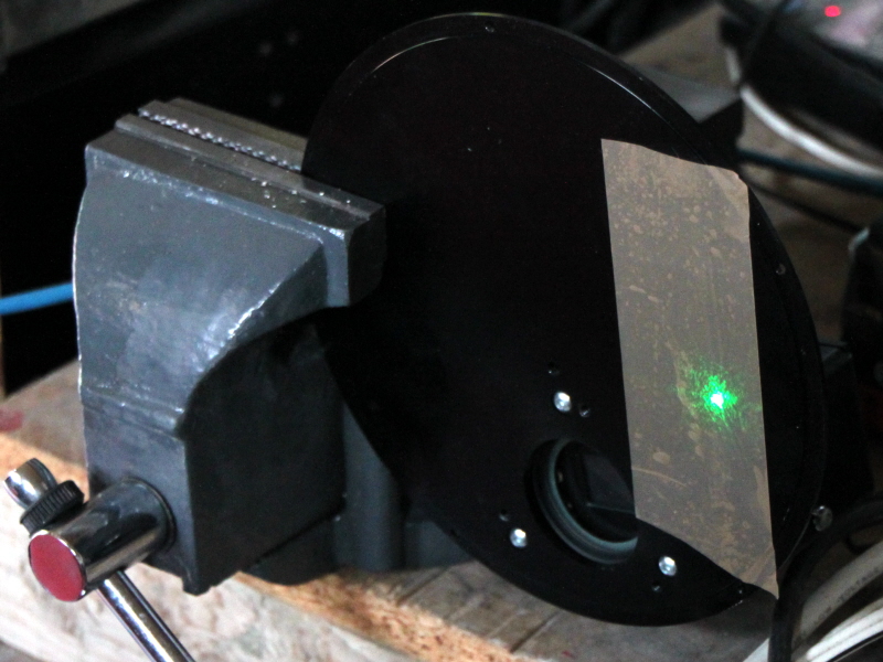
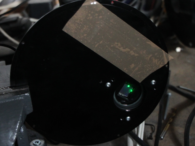
First, we need to ensure that the plate is accurately aligned with the laser. The black surface of the plate was not enough to reflect the laser in daytime, so I put some brown parcel tape on the plate to provide extra reflection.
Here is the plate with the brown parcel tape in place.
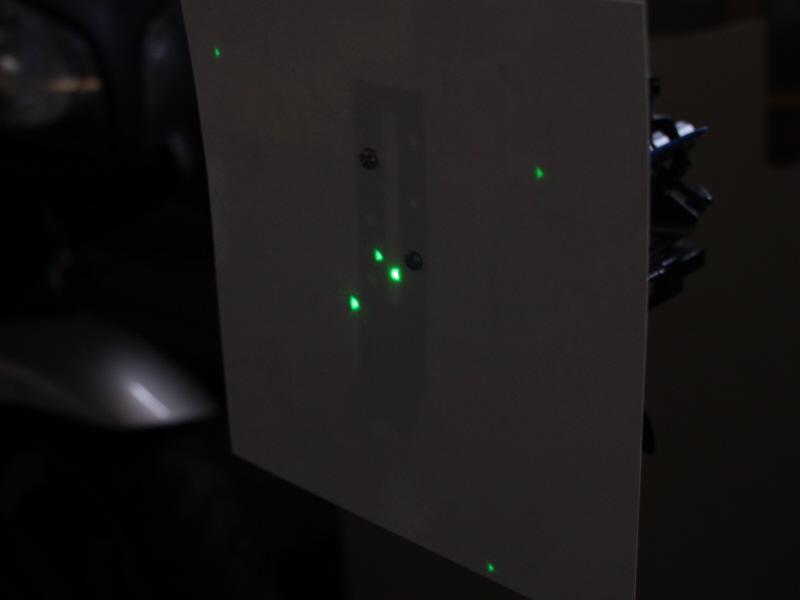
Here is the initial rough alignment by moving the tripod around.
Step 2: Plate in Alignment
Once the return from the chip is in line with the hole in the paper, the plate is aligned, and you are ready to move onto the next step.
Step 3: Rotate chip into line
Now undo the vice, and rotate the camera chip into the laser beam. If you have a shutter, like the SXVR-H18, then you will need to run a computer to open the shutter. The power supply isn't required for this though! I used 10 minute sub-exposures for my setup. You might think this would cause damage to the chip - I certainly was worried, and so checked with Terry Platt on the SX forum. He confirmed that there should be no problem with shooting a low power laser at the camera.
Step 4: Align the chip using the grubscrews
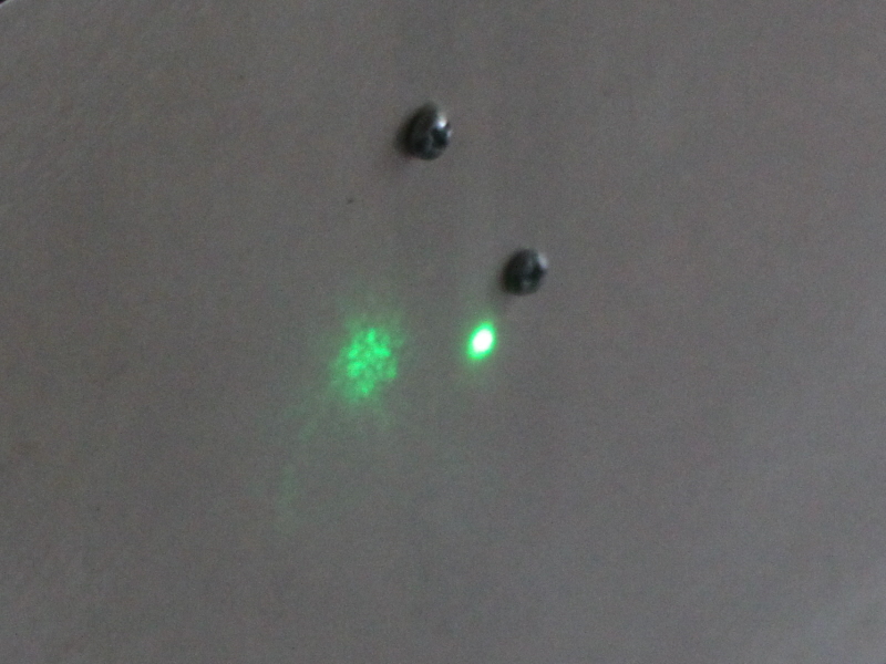
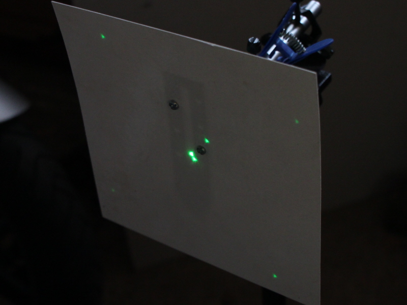
My initial rough alignment looked like this. The chip throws off a 5 point reflection. The sixth point nearest to the central spot on this picture is the glass reflection I believe.
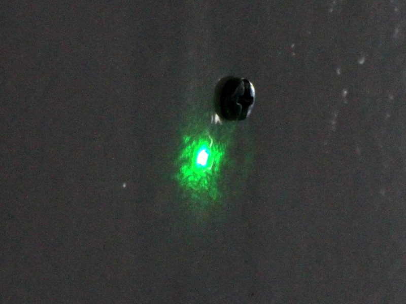
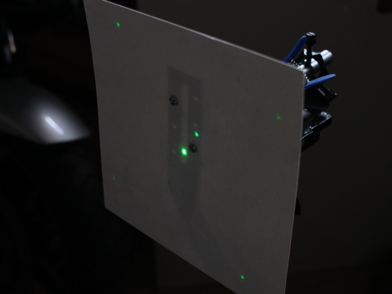
After tweaking the grubscrews, here is the camera almost in collimation.
A few final tweaks, and the central reflection is in alignment with the spot.
Voila! Your done :)
|